Espar Airtronic fault codes and Eberspacher Hydronic fault codes
When your Heater is acting up it will give out a fault code or error code to help you understand the problem. Find out what these codes mean and what you can do to remedy the problem.
No matter whether it’s a connectivity issue, fuel shortage, incorrect connections, under or over voltage, heaters show fault codes that can narrow down your investigation. However multiple fault codes can even cause a heater-lockout. Below is a list of all Espar Airtronic and Hydronic fault codes with explanations and potential remedies.
|
|
The heater has a fault that can only be repaired by a specialist. |
Visit an authorised Eberspächer Workshop. There are faults stored in memory. |
|
|
The heater control box was undervoltaged without interruption for at least 20 seconds. |
Check the battery for a drop in voltage. Charge battery or replace, if necessary. |
|
|
Overvoltage applied at the heater control box without interruption for at least 20 seconds. |
Check battery and replace, if necessary. |
|
|
Fault in the fuel supply or fuel pump. |
Check connection and cables for continuity, short circuit and damage. Pull the plug off the metering pump and inspect for damage. Check the fuel level in the fuel tank. If the fault cannot be remedied, please contact Eberspächer Support. |
|
|
With water heaters only: Water temperature in the heater too high. |
Check the water pump for proper function. Check the water circulation in the water circuit. The heater can be reset to the delivery condition by removing the heater fuse. If the fault cannot be remedied, please contact Eberspächer Support. Installation instructions | EasyStart Pro 22.1000.35.2203.0A EN |
|
|
With air heaters only: Air temperature in the heater too high. |
Check the air lines. Are air lines clogged or kinked? Air all air louvres free? The heater can be reset to the delivery condition by removing the heater fuse. If the fault cannot be remedied, please contact Eberspächer Support. |
|
|
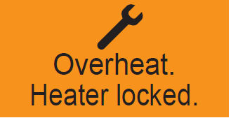
Overheating of the heater detected. The heater is interlocked for safety reasons. |
The heater can be reset to the delivery condition by removing the heater fuse. If the fault cannot be remedied, please contact Eberspächer Support. |
|
|
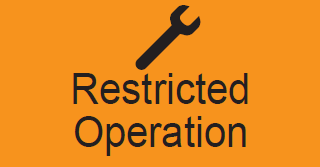
Emergency running of the heater. |
There is a fault in the heater. Restricted operation is still possible, however (with air heaters with target temperature 20°C). If the fault cannot be remedied, please contact Eberspächer Support. |
|
|
The external temperature sensor is defective. |
Check the wiring of the external temperature sensor for continuity,short-circuit or damage; replace the temperature sensor, if necessary. If the fault cannot be remedied, please contact Eberspächer Support. |
|
|
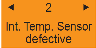
The internal temperature sensor is defective. |
There is no remedy for this fault. The control unit has to be replaced. |
|
|
The operating button is blocked. |
Can the operating button be freed again by hand? If the fault cannot beremedied, please contact Eberspächer Support. |
|
|
The button is blocked. |
Can the button be freed again by hand? If the fault cannot be remedied, please contact Eberspächer Support. |
|
|
Data are missing for EasyStart Pro for initial commissioning. |
Disconnect EasyStart Pro from the power supply and connect again. If the fault cannot be remedied, please contact Eberspächer Support. |
|
|
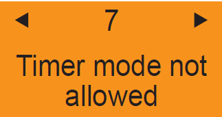
Timer mode is not permitted during ADR mode. |
Terminate ADR mode and test timer mode again. If the fault cannot be remedied, please contact Eberspächer Support. |
|
|
The heater is in auxiliary heating mode via Switching Plus and cannot be operated via EasyStart Pro during this time. |
Terminate auxiliary heating mode via Switching Plus. |
|
|
Terminate auxiliary heating mode via Switching Plus. |
Inspect the wiring for cable breakages/short-circuits. If the fault cannot be remedied, please contact Eberspächer Support. |
|
Fault code P000… for EasyScan and TP 7.1 (if connected via CAN) (…) for TP 7 (LIN) P000100 (071) P000101 (072) P000102 (073) |
Overheating/air outlet sensor -Interruption -Short circuit -Short circuit to battery (+) |
Check overheating sensor. -Check cables for continuity, short circuit and damage. -Unplug connector XB2, measure the resistance between cable BN (chamber 3) and cable WH (chamber 6). -Measured values see page 34, in case of deviating values –> replace temperature sensor. |
|
P000110 (087) P000111 (088) P000112 (089) |
Water/air inlet error -Interruption -Short circuit -Short circuit to battery (+) |
Check the air inlet sensor for damage. – In case of visible damage –> replace the temperature sensor. – Unplug connector XB2, measure the resistance between cable BK (chamber 1) and BK (chamber 4). – For measured values - see page 34. Delete fault memory. – If the error continues to be displayed –> replace the temperature sensor. |
|
P00010A (051) |
Cold blowing – Timeout |
The combustion chamber has not cooled sufficiently for a restart. Check whether hot combustion air is drawn in. If not –> check flame sensor, see Fault code P000120 (064) and Fault code P000121 (065). |
|
P000114 (014) |
Possible risk of overheating (implausible signal) Note! Fault code P000114 (014) is displayed only if - the heater is in operation. - temperature reached at overheating sensor at least 80 °C. |
Temperature difference between the flame and overheating sensor is too large. For remedial action see Fault code P000115 (012). Check flame sensor. – Unplug connector XB2, measure the resistance between cable BU (chamber 2) and cable BN (chamber 3). – Measured values see page 34, in case of deviating values –> replace temperature sensor. |
|
P000115 (012) |
Overheating - Software threshold exceeded |
Check air throughput Check overheating sensor – Check cables for continuity, short circuit and damage. – Unplug connector XB2, measure the resistance between cable BN (chamber 3) and cable WH (chamber 6). – Measured values see page 34, in case of deviating values –> replace temperature sensor. |
|
P000116 (017) |
Overheating - Hardware threshold exceeded |
Temperature at overheating sensor >150 °C For remedial action, see Fault code P000115 (012). Check overheating sensor. – Check cables for continuity, short circuit and damage. – Unplug connector XB2, measure the resistance between cable BN (chamber 3) and cable WH (chamber 6). – Measured values see page 34, in case of deviating values –> replace temperature sensor. |
|
P00011A (015) |
Operating lock-out - Too many overheating events detected |
The control box is locked due to too frequent consecutive overheating (Fault code P000114 (014), Fault code P000115 (012)). For remedial action see Fault code P000114 (014), Fault code P000115 (012). Unlock control box, see Chapter 4.3, p. 18. |
|
P000120 (064) P000121 (065) P000122 |
Flame sensor - Interruption - Short circuit - Short circuit to battery (+) |
Check flame sensor. - Check cable for continuity, short circuit and damage. – Unplug connector XB2, measure the resistance between cable BU (chamber 2) and cable BN (chamber 3). – Measured values see page 34, in case of deviating values –> replace the temperature sensor. Further display Fault code P000120 (064) and Fault code P000121 (065) –> replace the control box, see Chapter 5.4.2, p. 30. |
|
P000125 (057) P000126 (053) P000127 (054) P000128 (055) P000129 (056) |
Flame cutout from start process Flame cutout within the control range: 0% – 25% 25% – 50% 50% – 75% 75% – 100% Note! In case of flame cutout during the start phase or in normal operation the heater is restarted (max. 5 times). If the restart was successful, the fault code display is deleted. |
Check exhaust and combustion air system. Check fuel quantity and fuel supply, see Chapter 5.6, p. 42. Check flame sensor, see Fault code P000120 (064) and Fault code P000121 (065). |
|
P00012A (052) |
Unsuccessful starting process |
Check exhaust and combustion air system. Check fuel quantity and fuel supply, see Chapter 5.6, p. 42. Check the fuel filter or fuel strainer in the metering pump, renew if necessary. |
|
P00012B (050) |
Operating lockout, too many unsuccessful starting processes. |
Following 10 unsuccessful start attempts the control box is locked. Unlock control box, see Chapter 4.3, p. 18. Check fuel quantity and fuel supply, see Chapter 5.6, p. 42. |
|
P000130 (060) |
External air temperature sensor (LEF2) - Interruption |
Test external air inlet sensor Disconnect the GYRD / BNWH plug-in connection of the external temperature sensor and measure the resistance value, diagram and table of values see page 17, – if temperature sensor is ok, re-connect the GYRD / BNWH plug-in connection. Disconnect connector XS10/XB10 at the heater and measure the resistance value between PIN 5 GRRD and PIN 6 BNWH in connector housing XB10. – In the event of interruption/damage, the ohmic resistance value is outside the characteristic (for table, see on page 17). If the error continues to be displayed, test the connection to connector XS12/XB12. If resistance value is ok –> replace control box. |
|
P000131 (061) P000132 |
External air temperature sensor (LEF2) – Short circuit – Short circuit to battery (+) |
Test external air inlet sensor Disconnect the GYRD / BNWH plug-in connection of the external temperature sensor and measure the resistance value, diagram and table of values see page 17, – if ok, re-connect the GYRD / BNWH plug-in connection. Disconnect connector XS10/XB10 at the heater and measure the resistance value between PIN 5 GRRD and PIN 6 BNWH in connector housing XB10. – In the event of interruption/damage, the ohmic resistance value is outside the characteristic (for table, see on page 17) If the error continues to be displayed, test the connection to connector XS12/XB12. If the error P000131 (061) continues to be displayed → replace control box. |
|
P000143 (006) |
Air pressure sensor - Implausible signal |
Delete error and try again. If error occurs again, replace control box. |
|
P000150 P000151 P000152 |
Circuit board temperature sensor in the control box – defective (voltage too high) – defective (voltage too low) – Overtemperature detected |
Delete error and try again. Replace control box, see Chapter 5.4.2, p. 30. |
|
P000160 P000161 P000162 |
Setpoint transmitter (e.g. mini controller) – Interruption – Short circuit – Short circuit to battery (+) |
Check the setpoint transmitter (e.g. mini controller) Disconnect plug-in connection GYRD / BNWH of the setpoint transmitter (e.g. mini controller). The mini controller must be supplied with voltage and the heating switched on to enable a resistance to be measured. Therefore: – Disconnect the plug-in connection GYRD / BNWH to the mini controller, switch on mini controller “Heat” and measure the resistance value – 12V: 1,7 kohm (cold) up to 2.2 kohm (warm) -> equals the nominal value Disconnect plug-in connection XS10 / XB10 and measure the continuity of the GYRD / BNWH cable between connector XB10 and plug-in connection to the mini controller. – In the event of cable harness interruption/damage, replace or repair. If the error continues to be displayed, test the connection to connector XS10/XB10. If resistance value is ok –> replace control box. |
|
P000200 (048) P000201 (047) |
Metering pump - Interruption - Short circuit |
Check metering pump lead harness for continuity, short circuit and damage. - Lead harness ok –> renew the metering pump. |
|
P000202 (049) |
Metering pump Short circuit to battery (+) or transistor error |
Check cables for continuity, short circuit and damage. Note! Disconnect the connector at the metering pump for the cable test. With metering pump disconnected, check whether error P00202 continues to occur. If yes –> replace the cable harness. If not –> replace the metering pump. Display Fault code P000200 (048) metering pump defective –> replace metering pump. |
|
P000210 (020) P000211 (021) P000212 (022) |
Glow plug – Interruption – Short circuit – Short circuit to battery (+) or transistor error Caution! Damage to unit in case of overvoltage A voltage > 9.5 V (19 V for 24 V) irreparably damages the glow plug. -> Test the function with max 9.5 V (19 V for 24 V). Note! Note the short-circuit withstand capability of the power pack. |
Check glow plug. – Check cables for continuity, short circuit and damage. – Unplug connector -XB13, unclip cable WH (chamber 1) and cable BN (chamber 3). – For 12 V heater: Apply 9.5 V ±0.1 volt voltage to the glow plug and measure the current intensity after 25 seconds. – If measured value is 9.5 A (+1 / –1.5) the glow plug is ok. – In case of deviating values –> replace the glow plug. – For 24 V heater: Apply 19 V ±0.1 volt voltage to the glow plug and measure the current intensity after 25 seconds. – If measured value is 5.1 A (+1 / –1.5) the glow plug is ok. – In case of deviating values –> replace the glow plug. |
|
P000213 (019) |
Glow plug - Ignition energy too low |
Glow plug energy input is too low. Check cables for continuity, short circuit and damage. Test glow plug, see Fault code P000210 (020) to Fault code P000212 (022). |
|
P000220 P000221 P000222 |
Burner motor – Interruption – Short circuit – Short circuit downstream of +Ub or transistor fault/span> |
Visual inspection of electric motor / control box (contacting). Check the electric motor for dirt / corrosion, clean if necessary. Check the impeller for blockage, remove the blockage if necessary. Renew the burner motor if necessary. |
|
P000223 (034) P000224 (035) |
Burner motor – Blocking – Power input too high |
Impeller blocked (frozen, soiled, sluggish, ...). Remove blockage. – Check the burner motor for smooth and easy running by turning the impeller manually. Further display Fault code P000222. Renew fan, see Chapter 5.4.10, p. 35. |
|
P000260 P000261 P000262 |
Switch output – Interruption/span> – Short circuit – Short circuit to battery (+) or transistor error |
Test the switch output. Test WHRD conductor for continuity, short circuit and damage. If cable ok –> replace control box. Option: Delete errors and switch on the heater. If the error occurs again –> replace the control box |
|
P000280 P000281 P000282 |
Switch output (e.g. in configuration as fresh air damper) – Interruption – Short circuit to ground – Short circuit to battery (+) or transistor error |
Test the switch output. Test WHRD conductor for continuity, short circuit and damage. If cable ok –> replace control box. Option: Delete errors and switch on the heater. If the error occurs again –> replace the control box |
|
P000300 (074) |
Overheating detection Metering pump hardware or cutout circuit defective |
Test air outlet sensor. – Check cables for continuity, short circuit and damage. – Unplug connector XB2, measure the resistance between cable WH (chamber 6) and cable BN (chamber 3). – Measured values see page 34, in case of deviating values –> renew combination sensor. Further display Fault code P000300 (074) –> replace the control box. Unlock control box, see Chapter 4.3, p. 18. |
|
P000301 (090) P000302 (090) |
Watchdog reset Internal error on initialising the control box Too many watchdog resets |
Delete errors, the heater remains ready for operation. Test the power supply (voltage drops < 5 V and longer than 10 ms or < 8 V and longer than 10 ms, battery isolating switch, battery management system) Replace control box, see Chapter 5.4.2, p. 30. |
|
P000303 (099) |
Operating lockout: Too frequent output stage errors |
Replace control box, see Chapter 5.4.2, p. 30. |
|
P000304 (091) |
Too many resets (loose contact) |
Replace control box, see Chapter 5.4.2, p. 30. |
|
P000305 (095) |
Control box not calibrated |
Replace control box, see Chapter 5.4.2, p. 30. |
|
P000306 (098) |
Second cutout circuit is defective |
Replace control box, see Chapter 5.4.2, p. 30. |
|
P000307 (081) |
CAN communication error in control unit |
Delete errors and disconnect heater from the power supply. In the event of renewed occurrence of the error –> Test the control unit, test the cables to the control unit. |
|
P00030A |
CAN communication error |
Delete error. Heater remains ready for operation. |
|
P000310 (010) P000311 (010) |
Control box cutout due to overvoltage Heater cutout due to overvoltage Note! Heater is not functioning. |
Overvoltage applied at the control box without interruption for at least 20 seconds (factory setting). Unplug connector -XB10 at the heater. Start the vehicle engine. Measure voltage between cable RD (chamber 4) and cable BN (chamber 2). – Airtronic 12 volt voltage > 16 V (factory setting) → test the generator controller – Airtronic 24 volt voltage > 32 V (factory setting) → test the generator controller – Check the battery. |
|
P000312/3 (011) |
Control box cutout due to undervoltage Heater cutout due to undervoltage Note! Heater is not functioning. |
Undervoltage applied at the control box without interruption for at least 20 seconds (factory setting). Unplug connector -XB10 at the heater. Measure voltage between cable RD (chamber 4) and cable BN (chamber 2). – Airtronic 12 volt voltage < 10 V (factory setting) → test the generator controller. – Airtronic 24 volt voltage < 21 V (factory setting) → test the generator controller. – Check the fuses, the supply cables, the ground connections and the positive terminal post at the battery for voltage drop (corrosion). |
|
P000330 (092) |
ROM error |
Replace control box, see Chapter 5.4.2, p. 30. |
|
P000331 (093) |
RAM error |
Replace control box, see Chapter 5.4.2, p. 30. |
|
P000332 (094) |
NVMEM error (EEPROM, DataFlash) |
Replace control box, see Chapter 5.4.2, p. 30. |
|
P000333 |
AD converter error |
Replace control box, see Chapter 5.4.2, p. 30. |
|
P000342 |
Invalid configuration |
Impermissible combination of the Eberspächer products in the CAN system. – too many CAN heaters (more than 2) – too many CAN control units (more than 2) – only 1 heater and 1 control unit allowed for ADR In the ADR case, check the ADR coding in the EasyStart Pro via EasyScan If necessary, check the connection to the control element. If the error only appears in the error memory (passive), it can be ignored and deleted as it does not restrict the function of the heater. |
|
P000343 |
Parameter dataset is incompatible |
Replace control box, see Chapter 5.4.2, p. 30 |
|
P000394 |
ADR button – Short circuit |
Test ADR button. – Check the cables at GYRD / BNWH for continuity, short-circuit and damage. – Check the button for continuity, short circuit and damage. – If cables ok –> replace control box. |
|
P000440 (083) |
Timeout, communication with control unit |
Delete errors and disconnect heater from the power supply. In the event of renewed occurrence of the error –> Test the control unit, test the cables to the control unit. If error occurs again –> replace control unit. |
|
P000441 |
Timeout during communication with LIN control unit (only CI-bus communication) |
Delete errors and disconnect heater from the power supply. In the event of renewed occurrence of the error –> Test the control unit, test the cables to the control unit. |
|
P000450 |
LIN communication error (only CI-bus communication) |
Delete errors and disconnect heater from the power supply. In the event of renewed occurrence of the error –> Test the control unit, test the cables to the control unit. |
|
P001700 |
No heater connected to the CAN bus |
Check cable connections and power supply of the heater. |
|
P001701 |
Change device at the CAN bus (mismatch) |
The system configuration has changed – possible causes: – a heater has been replaced – a control unit has been removed – a control unit has been added Confirm error message via the operating button. New initialisation starts automatically. |
|
P001702 P001703 |
External temperature sensor is defective (short circuit or interruption) |
Check the cable for damage Check the connection to the external sensor at the control unit Renew sensor if necessary |
|
P001707 P001708 |
Internal temperature sensor is defective (short circuit or interruption) |
Internal hardware fault: The sensor can no longer be used as a display or control sensor. Replace control unit if necessary. |
|
P00170C |
Operating button is blocked |
Remove blockage Check operating button for dirt Replace control unit if necessary |
|
P001706 |
Back button is blocked |
Remove blockage Check operating button for dirt Replace control unit if necessary |
|
P00170A |
Timer is not calibrated |
Production error: Perform software update with EasyStart Pro or replace control unit. |
|
P001709 |
Missing data |
Production error: Perform software update with EasyStart Pro or replace control unit. |
|
P001704 |
Fatal internal error |
Production error: Perform software update with EasyStart Pro or replace control unit. |
|
P001705 |
External flash is defective |
Production error: Perform software update with EasyStart Pro or replace control unit. |
|
P00170B |
Invalid system configuration |
Check connected components (heaters and control units), an impermissible system configuration exists: – more than 2 control units are installed – more than 2 heaters are installed – an ADR heater is installed, the control unit does not support the ADR function. |